delfim pedrosa
industrial electronics and computers eng.
industrial electronics and computers eng.
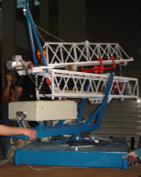
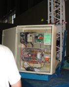
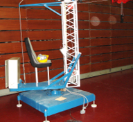
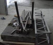
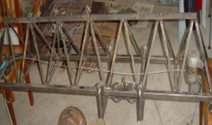
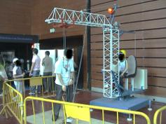
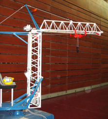 In 2006 I designed and developed a miniature of a tower crane that was integrated on electricity workshop. It took place in parallel with the national robotics festival - Robótica 2006. The crane has a height of 3 m and a length of 2.5 m, making a weight of 395 kg. Making possible a suspension of 80 kg, a height of 2 m, from the ground. The crane is foldable to facilitate its displacement between events. The crane was built to be didactic, where the user could transport pieces of steel from one place to another through an electromagnet. On the crane rotating base exist a seat, where the user can sit down and operate the crane by the commands in your front. For safety reasons, the crane is limited to a working area and it has a remote control that turns off the controls. For the construction of the crane was used steel square tubes, steel angles, flat steel bar, diamond plate steel and steel C section purlins. For the rotation system was used a semi-trailer axle hub. The crane is operated using three induction motors and respective gearboxes, and an electromagnet. The control system consists of an emergency button, a two-position joystick, a four-position joystick, and an illuminated pressure switch. The two-position joystick, it is used to up/down the pieces, controls a frequency inverter that drives the respective induction motor. The limits are obtained with an inductive sensor that is connected to a microcontroller that, at the limits, disables the command from the joystick. The four-position joystick controls the base rotation and the movement forwards/backwards of the pieces. The joystick does not allow the two motors to operate at the same time, because only using one frequency inverter to control both motors. The motor selection is made through the selection of two contactors that they are connected with the frequency inverter output. The illuminated pressure switch is used to turn on/off the electromagnet. When the electromagnet is active, the light is on. With the information of the height of the electromagnet (microcontroller), the electromagnet only is turn off if the height from the floor is less than 50 cm (safety questions).
The construction process and the operating principle can be seen in this paper: "Foldable slewing crane".

 In 2006 I designed and developed a universal series motor that was integrated on electricity workshop. It took place in parallel with the national robotics festival - Robótica 2006. This type of motors is called universal because they can work with direct and alternating current. The motor was developed with the didactic intention. This project intends to make known the fundamentals of electromagnetism that are the basis of the principle of operation of the electric motors. In this sense, the construction of the motor is basic, to demonstrate that anyone can assemble their universal series motor. The developed motor is powered by a 12 V DC voltage source. The motor starts whenever the large pressure switch is activated.
The construction process and the operating principle can be seen in this paper: "Handmade series direct current motor".
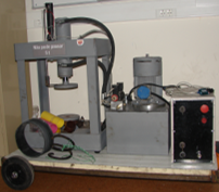 The construction of the hydraulic press emerged during the course unit of integrated laboratories and practice II of the 3rd year (2007) that proposed to develop a control and data acquisition system for a testing machine. The work was carried out by some groups of six elements. I decided to build the press because only exists one press in the laboratory for all groups, it is based on ball screw that is driven by an induction motor with gearbox. With this press, it was necessary to always be assembling and disassembling the electronic system developed by each group. In conversation with the rest of the group, we decided to develop our press. As most members of the group had never had contact with a hydraulic system, we decided to make a press with a hydraulic cylinder. Thus, the project became more similar to the existing testing machine. In the final project, a personal computer was used to monitor and activate the intended resistance tests of the material. To measure the exerted force on the material to be tested, the press had a load cell underside. The cylinder position was obtained through a linear encoder, recycled from a printer. To control the hydraulic flow, the induction motor, that operates the hydraulic pump, was controlled using a frequency inverter. All of the sensors and actuators were controlled using a PLC. The PLC was configured with a PID control to adjust the desired load to the material under test. It also developed an application in LabVIEW to save the load and deformation that was occurring during the test.
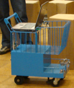 The construction of the shopping cart emerged during the course unit of integrated laboratories and practice I of the 3rd year (2006). It was proposed, for each group with six elements, to develop an autonomous mobile robot. The group decided to make a shopping cart that followed the user in the supermarket or the car traced a route inside the supermarket according to the shopping list of the user. The robot had a personal computer where the user entered the shopping list and then the cart forwards user through the supermarket. This functionality was accomplished through the use of distance and position sensors. Two wiper motors were used to make the traction system. The cart had a 12 V car battery that powered the traction system, sensors and computer. As previously mentioned, the cart also followed the user, mainly designed for users with reduced mobility. For the project, the group also developed the control and drive printed circuit boards (PCB) for the electric motors, as well as the signal conditioning PCB for the sensors in the robot.
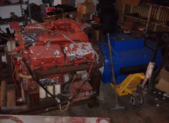
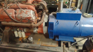
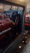
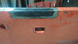
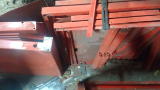
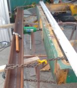
Development and repair of structures. Internal combustion engines repair. Adaptation of internal combustion engines to generators. Production and repair of switchboard for emergency generators.

Copyright © - All Rights Reserved - delfimpedrosa.pt