delfim pedrosa
industrial electronics and computers eng.
industrial electronics and computers eng.
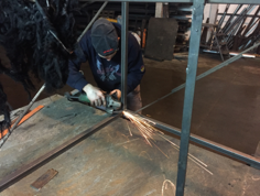
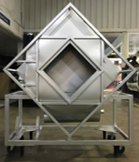
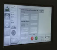
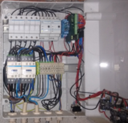
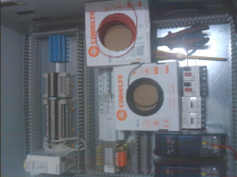
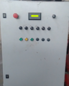
Collaborator with the Fafediesel in the development of a prototype of a cleaning particulate filters machine. It was developed the mechanical structure and the switchboard. As well the PLC programming and the graphical user interface that uses a 10.1" touchscreen. The developed switchboard has: one PLC; one power supply for sensors, relays and PLC; one power supply for stepper motor controllers; three controllers for stepper motors; relays and contactors; two frequency inverters, one for rotation system and another for vacuum pump; and circuit breakers. The PLC receives information from several inductive and analogue sensors acting on three induction motors and three stepper motors. For confidentiality reasons, I will only mention some aspects of the developed program for the PLC. The particle filter is placed in the workspace, the PLC receives the information that there is a filter to clean. Proceeding with a particle filter test. After obtaining the values, the cleaning of the particulate filter starts. After half an hour, the cleaning stops and a new test is performed, to compare the results before and after cleaning.
Development of a program for the automatic start of an emergency generator. The automatic start can occur in three situations: there is a power grid failure for half an hour; in 10 minutes there are at least 5 short-term power grid failures; or it received an external signal. When there is a start signal, the 12 V power is connected, followed by the start of the starter motor. The starter motor is running for 20 seconds without the combustion engine starting. If occurs three failed attempts, the system goes into protection and it does not start any more before reset. At the same time, an SMS is sent to notify the user. In case of correct operation, the power grid contactor is turned off and the generator contactor is turned on. The generator is turned off if the oil pressure fails, the alternator is not charging, excess of temperature, the power grid has been stable for at least 5 minutes, or due to fuel fail. In all cases, except with a stable power grid, the generator never starts again until the respective technical checks are made to verify what happened. In normal operation, the generator turns on and off when it is necessary.
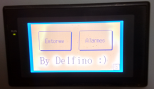
PLC and touchscreen panel programming to control electric roller shutters in a home. Modification of the electric roller shutters switchboard to add a PLC and touchscreen panel. The first step was developing the program for the PLC and touchscreen panel. The developed program allows controlling the roller shutters individually or all at the same time. It is possible to place the roller shutters in the middle of the windows, only in a ventilation position or to open/close all at the same time. The PLC also receives a signal from the alarm to close all roller shutters when the alarm is activated. On the touchscreen panel, it is possible to view the status of the roller shutters, open or closed. As soon as the roller shutters are no longer in operation, the power supply to the electric motors is switched off completely. The PLC also receives information from emergency switches that are strategically positioned in different rooms of the house, for example, bedrooms and bathrooms. When the switch is activated, an alert is displayed on the touchscreen panel and an internal bell is active for 30 seconds, after this time if the system is not reset an external bell is activated for another minute. Even so, if there is no system reset, an SMS is sent to the numbers previously configured in the GSM module. The PLC has a UPS to allow the user starts an emergency generator in case of a power grid fault. The second step consisted of removing all electrical components from the switchboard that it not be used with the PLC. Then, the assembly and the connections of the PLC in existing switchboard were done.
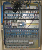
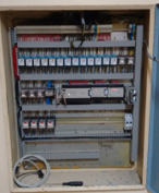
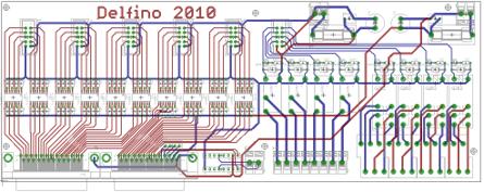
Development and assembly of home security systems with a PLC and GSM module. The assembly of the PLC, power supply, GSM module, connectors and printed circuit board developed were implement in a switchboard. The home security systems have several actuation zones, the most convenient zones are active with the use of the home. All doors and windows have sensors and glass breaks. There is a panel where several LEDs are located regarding the status of each sensor. As the PLC has a transistor outputs, a printed circuit board was developed to optically isolate the PLC outputs of the LEDs and relays for triggering the sirens. Some zones activate the closing of the electric roller shutters, as soon as leave the home. If the roller shutters are not closed within a certain time, an SMS is sent to the user. In the occurrence of an event, an SMS is sent to the users configured in the GSM module. Depending on the type of event and active zone, it can be existing a missed confirmation call. There is also a system that monitoring the battery voltage of the uninterruptible power supply (UPS), which in anomaly or low battery voltage activates the emergency generator. And much more.
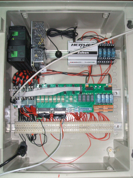
Programming a PLC to control the thickness of the wooden planks that are coming out of the chariot of the wood bandsaw. When the start is press, the PLC active the left movement of the chariot. When the chariot reaching the end of the course, the chariot stops, then the chariot is moved away from the bandsaw by half a centimetre. After moving away, the chariot is moved to the right side until it reaches the end of the course. After this, the chariot forwards the half a centimetre plus the specified thickness of the wooden planks. This cycle is repeated as long as the distance between the chariot and the bandsaw allows it to be safe.
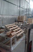
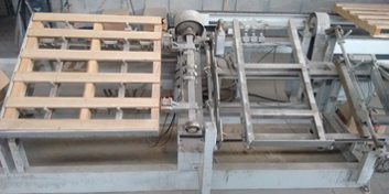
Photos coming soon.Collaborator with Premafe , in programming a PLC and HMI for a pallet machine. This project consisted of automating a pallet machine from the wood entry to the stacking of the final pallets. The user places the wooden beams and presses the start button, the wooden beams are fixed to the machine frame. Then it is active the superior spacer of the wooden planks. After placing and nailing the wooden planks, the user press again the start button to rotate the pallet to the workstation two. When it is at the workstation two the pallet is left and the frame returns to the starting position, workstation one, to start a new pallet. In the workstation two, it is active the inferior spacer of the wooden planks. When the wooden planks have been nailed, the user presses the start button for this station. The pallet is fixed to the frame that rotates it's to the output line. When the pallet is over the output line, the frame releases the pallet and returns to the station to receive another pallet. The output line contains rollers that pull the pallet up to the pallet elevator. When the pallet is reaching the elevator, the existing pallets are lifted and fixed. The pallets are stacked in the elevator. The elevator has the capacity of the 20 pallets. Exist two three-phase induction motors for rotating the pallet between stations. The motors are controlled with two frequency inverters, that are controlled by the PLC. There is a small HMI that allows the user to enter some parameters for the machine operation.
Copyright © - All Rights Reserved - delfimpedrosa.pt