delfim pedrosa
industrial electronics and computers eng.
industrial electronics and computers eng.
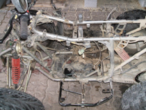
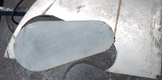
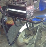
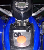
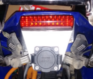
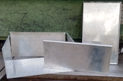
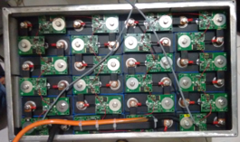
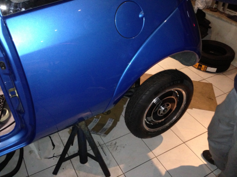
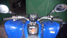 During the year 2014 I started the particular project of converting a 4 wheels motorcycle to electric. The conversion started with the removal of the Internal Combustion Engine (ICE) and all components related with the ICE. After I removed the ICE, the best place for the electric machine and batteries was analyzed. I already had the electric machine but I did not have the batteries. So, I chose to put the electric machine over the rear axle in order to take advantage of the central space in the motorcycle. The choice of batteries was the hardest part to deciding during the conversion, since I wanted the batteries to be neither too heavy nor expensive. The lithium batteries were the final choice, mainly due to the sales and it have low weight and low volume. With the HEINZMANN's axial-flow electric machine and the batteries, I started the purchase of the remaining electronic components needed for the conversion. Lithium batteries are very sensitive to their limits, specially the cell voltage. In this sense, I acquired a Battery Management System (BMS) from the company Albertronic B.V., Netherlands. I choice this BMS because it is not necessary to have a wire from each cell to the central unit. Each cell has an independent module that communicates with the central unit by one-wire communication. On the other hand, the BMS has also the advantage of communicating with the battery charger, that is purchased from the GWL POWER company, Czech Republic. The BMS ensures that the minimum and maximum voltage of each cell is not reached. If these limits are reached the system is turned off, as well as the maximum operating temperature. During the charging mode the BMS also equalizes the voltage of each cell. The electric machine controller was purchased from company Kelly Controls, China. In electric vehicles the negative wire of the traction batteries cannot be connected to the chassis of the vehicle. It is necessary an extra battery (service battery) to power the electric system of the vehicle. The service battery in vehicles with ICE is charged from the vehicle's alternator. In pure electric vehicles this battery is charged from the powertrain batteries. So, I bought an isolated DC/DC converter (because the negative wire of the powertrain batteries and the service battery cannot be the same). This DC/DC converter was also purchased from the company Kelly Controls, as well as the power contactor (cut the powertrain batteries), the fuses and the electronic throttle. In parallel with the purchases, I cutting the aluminum plate that join the electric machine with the motorcycle rear axle. At the same time, I cutting and bending the aluminum plates for the construction of the batteries box. The design of the box was developed in order of the number of cells and the type of association. It was associated 24 cells in series in order to obtain the final voltage of 77 V. The developed electric schematic allows the precharge of the controller (required due to the internal capacitors) and ensures that the system will not start if the direction selector is not in the neutral mode. To obtain the direction of the motorcycle (forwards or backwards) two switches was added in original selector. The space previously occupied by the fuel tank cap was used to put the emergency button and the gauge to show the instantaneous current of the electric machine. To connect the battery charger to motorcycle I bought a plug that is used to charge the electric vehicles. The plug is located in the place that previously occupied by the license plate. It was developed an aluminum plate to fix the plug. The electric schematic also ensures that the motorcycle does not start when the plug is connected.

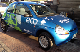 Collaborator with the Fafediesel in conversion of an internal combustion engine vehicle into an electric vehicle. The project called e-mob consisted of the conversion of a 1998 Ford KA into an electric vehicle. When I joined the project the main components for the conversion had already been acquired, they are: two in-wheel motors and their controllers, the electronic throttle, the lithium battery pack of 5.7 kWh and its charger. These components were purchased from the Portuguese company Sismelv. The electric machines were placed on the rear axle without change the original braking system of the vehicle. To approve later, one of the requirements is the original braking system cannot be altered. The power controllers are located at the place that it was previously occupied by the fuel tank. The battery pack and the charger are placed in the space previously occupied by the internal combustion engine. During the transformation process, it is necessary to pay attention to the maximum weight in each axle, because another requirement to approve is the permissible weight on each axle cannot be exceeded. Another requirement is the chassis of the vehicle which cannot be altered or weakened for the addition of the new components. The original gearshift also was changed. The gearshift has been changed to only three positions: forward, neutral and backward. The gearshift has mechanical interlocking to prevent the change between the forward and backward positions without it goes before to neutral position. The vehicle only goes to read state if the gearshift is in the neutral position, the emergency button is not active, the brake pedal is pressed and the charging plug is not connected. The vehicle also has an inertia switch to turn off the battery pack if the vehicle has an accident.
The presentation of the project happened on May 11th, 2013 during the celebrations of the 27th anniversary of Fafediesel.
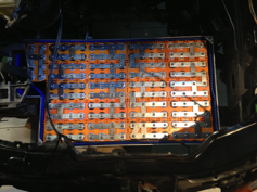
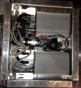
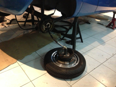
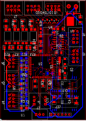
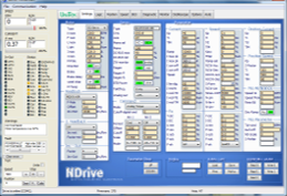
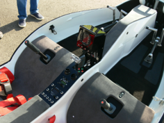
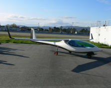
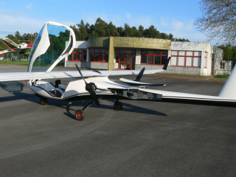
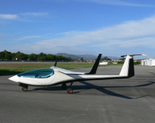 Collaborator with the eurosportaircraft in the development of the electronics systems to control the electric motors on the Crossover, 2013 version. My contribution to this project consisted of designing and implementing the electrical scheme. It also executed the design and development of all printed circuit boards for the control of all existing electric motors. The Crossover has 15 electric motors: two motors for the propellers, two motors for retracting the propellers, two motors for the propellers covers, three motors for the landing gear, two motors for the landing gear covers, one motor for the flap control, two motors for adjusting the rudder pedals and one motor for the canopy. To retract the propellers, the controllers change their algorithm control from torque control to position control. This change is necessary to ensure that the propellers always stop in the same position to go inside of the frame of the motor glider. When the propellers are in the position, the propeller covers open and the arms with the propellers go into the frame. After the propellers are inside the covers close again. The same procedure is performed to place the propellers outside but in the opposite order. To extract the landing gear, it is initially verified, by a sonar, if the ground is near the motor glider. If not exists ground the landing gear covers open and the landing gear arms go out of the frame. In the end, the landing gear covers close again. To retract the landing gear, it is verified if the ground is near the motor glider. The same procedure is performed to extract the landing gear but in the opposite order. To open the canopy one press is enough on the inside press button or remote control. On the other hand, to close the canopy is necessary to keep the button pressed, to ensure that not exists any object between the canopy and the frame. All these movements are controlled from the microcontroller that it was located on the developed printed circuit boards. The flaps position is also controlled by the microcontroller, where it can be chosen three pre-selected positions: cruise, take-off and landing. The microcontroller receives the execution instruction from the switches in the centre panel of the cockpit.
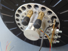
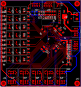
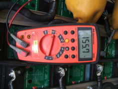
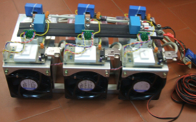
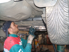
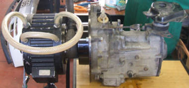
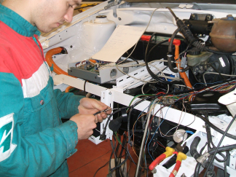
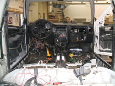
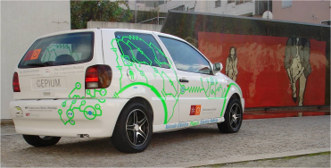 The Carro Elétrico Plug-In da Universidade do Minho was developed at GEPE and it uses the 1996 Volkswagen Polo as platform. This project started with my master dissertation, entitled "Desenvolvimento de um Veículo Eléctrico - Development of an Electric Vehicle". It was chosen this vehicle because it is one vehicle that has the highest weight ratio between the tare and gross weight and it does not have power steering. This ratio was important because it is used for gel batteries (lead-free maintenance). The conversion starts with the removal of the damaged internal combustion engine and all the components associated with it, for example, the fuel tank, the exhaust system, the gearbox and others. Currently, the electric machine is coupled with the gearbox through the clutch. Afterwards, it is intended that the electric machine is directly connected with the gearbox, the gearbox will work as reduction gear and differential. Since gel batteries are used, they are placed into two zones of the vehicle. The division ensures that the maximum permissible weight on each axle is not exceeded. Part of the batteries are located in the space previously occupied by the fuel tank and the other batteries were placed around the electric machine at the front of the vehicle. The batteries have a capacity of 9.5 kWh, and it is expected that the vehicle has the autonomy to make a trip between the Braga and Guimarães campus of the University of Minho. To ensure the correct working of the braking system, it was necessary to add an electric vacuum pump which was previously provided by the internal combustion engine. The electric machine controller was developed in my master dissertation.
Copyright © - All Rights Reserved - delfimpedrosa.pt